You simply need to know - Basics
In electromagnetism and electronics, inductance is the tendency of an electrical conductor to oppose a change in the electric current flowing through it. The flow......
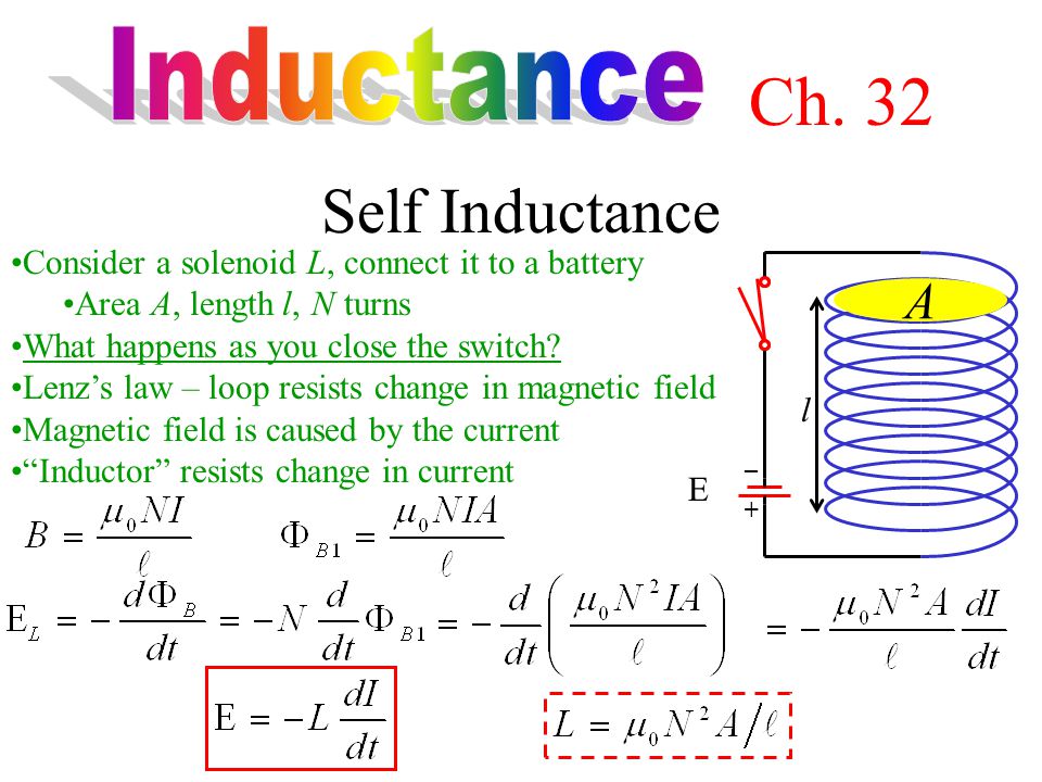
In electromagnetism and electronics, inductance is the tendency of an electrical conductor to oppose a change in the electric current flowing through it. The flow of electric current creates a magnetic field around the conductor. The field strength depends on the magnitude of the current, and follows any changes in current. From Faraday's law of induction, any change in magnetic field through a circuit induces an electromotive force (EMF) (voltage) in the conductors, a process known as electromagnetic induction. This induced voltage created by the changing current has the effect of opposing the change in current. This is stated by Lenz's law, and the voltage is called back EMF.
Inductance is defined as the ratio of the induced voltage to the rate of change of current causing it. It is a proportionality factor that depends on the geometry of circuit conductors and the magnetic permeability of nearby materials. An electronic component designed to add inductance to a circuit is called an inductor. It typically consists of a coil or helix of wire.
The term inductance was coined by Oliver Heaviside in 1886. It is customary to use the symbol {\displaystyle L}L for inductance, in honour of the physicist Heinrich Lenz. In the SI system, the unit of inductance is the henry (H), which is the amount of inductance that causes a voltage of one volt, when the current is changing at a rate of one ampere per second. It is named for Joseph Henry, who discovered inductance independently of Faraday.
History
The history of electromagnetic induction, a facet of electromagnetism, began with observations of the ancients: electric charge or static electricity (rubbing silk on amber), electric current (lightning), and magnetic attraction (lodestone). Understanding the unity of these forces of nature, and the scientific theory of electromagnetism began in the late 18th century.
Electromagnetic induction was first described by Michael Faraday in 1831. In Faraday's experiment, he wrapped two wires around opposite sides of an iron ring. He expected that, when current started to flow in one wire, a sort of wave would travel through the ring and cause some electrical effect on the opposite side. Using a galvanometer, he observed a transient current flow in the second coil of wire each time that a battery was connected or disconnected from the first coil. This current was induced by the change in magnetic flux that occurred when the battery was connected and disconnected. Faraday found several other manifestations of electromagnetic induction. For example, he saw transient currents when he quickly slid a bar magnet in and out of a coil of wires, and he generated a steady (DC) current by rotating a copper disk near the bar magnet with a sliding electrical lead ("Faraday's disk").
In condensed matter physics, magnetic anisotropy describes how an object's magnetic properties can be different depending on direction. In the simplest case, there is no......
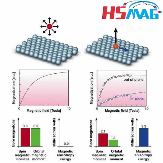
In condensed matter physics, magnetic anisotropy describes how an object's magnetic properties can be different depending on direction. In the simplest case, there is no preferential direction for an object's magnetic moment. It will respond to an applied magnetic field in the same way, regardless of which direction the field is applied. This is known as magnetic isotropy. In contrast, magnetically anisotropic materials will be easier or harder to magnetize depending on which way the object is rotated.
For most magnetically anisotropic materials, there are two easiest directions to magnetize the material, which are a 180° rotation apart. The line parallel to these directions is called the easy axis. In other words, the easy axis is an energetically favorable direction of spontaneous magnetization. Because the two opposite directions along an easy axis are usually equivalently easy to magnetize along, and the actual direction of magnetization can just as easily settle into either direction, which is an example of spontaneous symmetry breaking.
Magnetic anisotropy is a prerequisite for hysteresis in ferromagnets: without it, a ferromagnet is superparamagnetic.
Sources
The observed magnetic anisotropy in an object can happen for several different reasons. Rather than having a single cause, the overall magnetic anisotropy of a given object is often explained by a combination of these different factors:
Magnetocrystalline anisotropy
The atomic structure of a crystal introduces preferential directions for the magnetization.
Shape anisotropy
When a particle is not perfectly spherical, the demagnetizing field will not be equal for all directions, creating one or more easy axes.
Magnetoelastic anisotropy
Tension may alter magnetic behaviour, leading to magnetic anisotropy.
Exchange anisotropy
Occurs when antiferromagnetic and ferromagnetic materials interact.

We know magnets aren’t attracted to everything; if we put a magnet on a wooden wall, it will fall right down. Generally, magnets are attracted......
We know magnets aren’t attracted to everything; if we put a magnet on a wooden wall, it will fall right down. Generally, magnets are attracted to objects that are made of the metals iron, nickel, or cobalt. These materials are called ferromagnetic materials. The reason magnets stick to these metals is because of a special characteristic about the atoms inside these metals. In most other materials that are not magnetic, the magnetic moments of the atoms inside are all oriented in random directions that cancel each other out. In ferromagnetic materials, the atoms form structures called domains. A domain is a region inside of a material where groups of magnetic moments naturally align in the same direction.
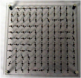
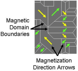
There can be numerous domains within an object. When there is no external magnetic field present, the domains are also oriented randomly so that there is no net magnetic field. However, when an external magnetic field is present, the domains will rotate and align with the external magnetic field. When all or most of the domains are aligned in the same direction, the whole object becomes magnetized in that direction and becomes a magnet.
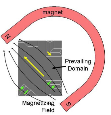
The process of using a magnetic field to magnetize another object is called induction. Once a magnet has been induced, it produces its own magnetic field as long as its domains are aligned.
What is a Magnetic Field?
The magnetic field is a field, produced by electric charges in motion. It is a field of......
What is a Magnetic Field?
The magnetic field is a field, produced by electric charges in motion. It is a field of force causing a force on material like iron when placed in the vicinity of the field. Magnetic field does not require any medium to propagate; it can propagate even in a vacuum.
Also, the energy storing capacity of the magnetic field is greater than the electric field, this distinguishes the magnetic field from the electric field, and therefore it is utilized in almost every electromechanical device like transformers, motors, and generators.
The earth also has its natural magnetism which protects it from solar waves from the sun. Further, it provides an operating field for a magnetic compass to operate.
Permanent magnets have their own magnetism, and they are made up of ferromagnetic material like iron or nickel or alnico alloys, while electromagnets are coils which produce the magnetic field when an electric current passes through the coil.

For example, a current carrying conductor produces a magnetic field around the conductor, whose direction is determined by Right-Hand Screw Rule and the strength of the field can be varied in accordance with the amount of current flowing in the conductor around the coil.
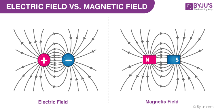
Electromagnets are utilized in various industries for various production and manufacturing processes. The magnetic field has both North pole and a South pole. Monopole does not exist for a magnetic field, unlike electric field where a charge can be isolated.
The field line forms a closed loop, as it emanates from North and terminates to South outside a magnet and from south pole to north pole inside a magnet.

At any point on the field, it has both magnitude and direction, so it is represented by a vector. Magnetic field finds its application in almost every electromechanical devices like electric motors and generators. When a current-carrying coil is placed in a magnetic field, it experiences a torque.
This principle of operation is utilised in electric motor where magnetic torque is produced which exerts a rotating torque on the rotor while in case of generators magnetic field provides a medium for energy exchange between stator and rotor via induction principle.
In case of a 3 phase motor, a rotating magnetic field is produced by the 3 phase windings displaced 120 degrees in space. A rotating magnetic field rotates with the synchronous speed in the air gap of machines which is required for synchronous motor and induction motors to operate.
In order to provide a magnetic medium, the machine draws a magnetizing current which degrades the power factor of the system. Poor power factor increases the burden on the power system components like transformer and generators, but it is an equally essential component for almost every electromechanical device to operate.

Magnetic Field Strength refers to one of two ways that the expression of a magnetic field can take place. It is certainly different from the......
Magnetic Field Strength refers to one of two ways that the expression of a magnetic field can take place. It is certainly different from the magnetic flux density. Furthermore, the formation of a magnetic field takes place when a wire carries an electric current. The direction of the magnetic field is dependent on the direction of the current. The visualization of the magnetic field can take place as field lines. Also, the magnetic field strength definitely corresponds to the density of the field lines.
Magnetic field strength refers to the ratio of the MMF which is required to create a certain Flux Density within a certain material per unit length of that material. Some experts also call is as the magnetic field intensity.
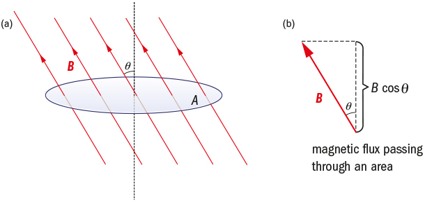
Furthermore, the magnetic flux refers to the total number of magnetic field lines that penetrate an area. Furthermore, the magnetic flux density tends to diminish with increasing distance from a straight current-carrying wire or a straight line which connects a pair of magnetic poles around which the magnetic field is stable.
Magnetic field strength refers to a physical quantity that is used as one of the basic measures of the intensity of the magnetic field. The unit of magnetic field strength happens to be ampere per meter or A/m.
Furthermore, the symbol of the magnetic field strength happens to be ‘H’. Magnetic field strength is a quantitative measure of strength or the weakness of the magnetic field. Also, it is the force which a unit north pole of one-weber strength experiences at a particular point in the magnetic field.
All magnets, no matter what their shape, have two regions called magnetic poles with the magnetism both in and around a magnetic circuit producing a......
All magnets, no matter what their shape, have two regions called magnetic poles with the magnetism both in and around a magnetic circuit producing a definite chain of organised and balanced pattern of invisible lines of flux around it. These lines of flux are collectively referred to as the “magnetic field” of the magnet. The shape of this magnetic field is more intense in some parts than others with the area of the magnet that has the greatest magnetism being called “poles”. At each end of a magnet is a pole.
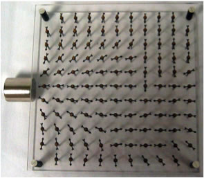
These lines of flux (called a vector field) can not be seen by the naked eye, but they can be seen visually by using iron fillings sprinkled onto a sheet of paper or by using a small compass to trace them out. Magnetic poles are always present in pairs, there is always a region of the magnet called the North-pole and there is always an opposite region called the South-pole.
Magnetic fields are always shown visually as lines of force that give a definite pole at each end of the material where the flux lines are more dense and concentrated. The lines which go to make up a magnetic field showing the direction and intensity are called Lines of Force or more commonly “Magnetic Flux” and are given the Greek symbol, (Φ).
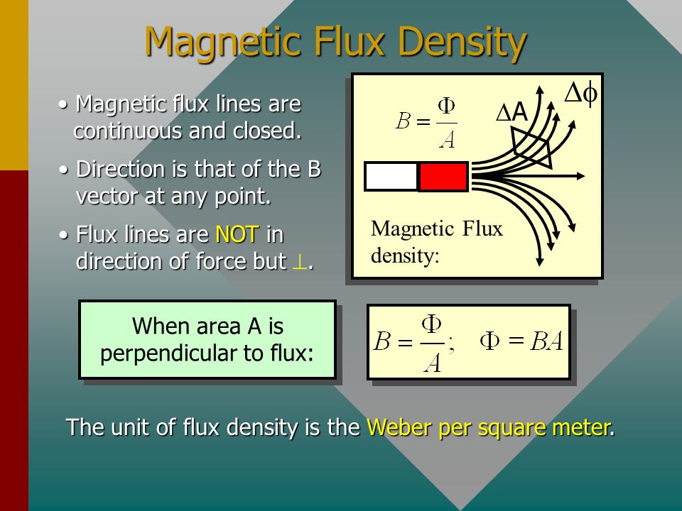
Magnetic flux density B
The flux density is the number of magnetic field lines that pass through a certain point on a surface. The SI......
Magnetic flux density B
The flux density is the number of magnetic field lines that pass through a certain point on a surface. The SI unit is T (tesla), which is equal to weber per square metre (Wb/m2). The unit in the CGS system is G (gauss). 1 tesla is equal to 10,000 gauss.
At any given point in a magnetic field, you can see the magnetic flux density as a vector in the field direction with a magnitude equal to the Lorentz force that an electrical wire experiences when it is oriented perpendicular to the field lines.
The higher the flux density, the stronger the magnet is at that point and thus the better it can hold iron particles at that point.
The Magnetic Hysteresis loop, shows the behaviour of a ferromagnetic core graphically as the relationship between B and H is non-linear. Starting with an unmagnetised core both B and H will be at zero, point 0 on......
The Magnetic Hysteresis loop, shows the behaviour of a ferromagnetic core graphically as the relationship between B and H is non-linear. Starting with an unmagnetised core both B and H will be at zero, point 0 on the magnetisation curve. If the magnetisation current, i is increased in a positive direction to some value the magnetic field strength H increases linearly with i and the flux density B will also increase as shown by the curve from point 0 to point a as it heads towards saturation. Now if the magnetising current in the coil is reduced to zero, the magnetic field circulating around the core also reduces to zero. However, the coils magnetic flux will not reach zero due to the residual magnetism present within the core and this is shown on the curve from point a to point b. To reduce the flux density at point b to zero we need to reverse the current flowing through the coil. The magnetising force which must be applied to null the residual flux density is called a “Coercive Force”. This coercive force reverses the magnetic field re-arranging the molecular magnets until the core becomes unmagnetised at point c. An increase in this reverse current causes the core to be magnetised in the opposite direction and increasing this magnetisation current further will cause the core to reach its saturation point but in the opposite direction, point d on the curve. This point is symmetrical to point b. If the magnetising current is reduced again to zero the residual magnetism present in the core will be equal to the previous value but in reverse at point e. Again reversing the magnetising current flowing through the coil this time into a positive direction will cause the magnetic flux to reach zero, point f on the curve and as before increasing the magnetisation current further in a positive direction will cause the core to reach saturation at point a. Then the B-H curve follows the path of a-b-c-d-e-f-a as the magnetising current flowing through the coil alternates between a positive and negative value such as the cycle of an AC voltage. This path is called a Magnetic Hysteresis Loop.
The effect of magnetic hysteresis shows that the magnetisation process of a ferromagnetic core and therefore the flux density depends on which part of the curve the ferromagnetic core is magnetised on as this depends upon the circuits past history giving the core a form of “memory”. Then ferromagnetic materials have memory because they remain magnetised after the external magnetic field has been removed. However, soft ferromagnetic materials such as iron or silicon steel have very narrow magnetic hysteresis loops resulting in very small amounts of residual magnetism making them ideal for use in relays, solenoids and transformers as they can be easily magnetised and demagnetised. Since a coercive force must be applied to overcome this residual magnetism, work must be done in closing the hysteresis loop with the energy being used being dissipated as heat in the magnetic material. This heat is known as hysteresis loss, the amount of loss depends on the material’s value of coercive force. By adding additive’s to the iron metal such as silicon, materials with a very small coercive force can be made that have a very narrow hysteresis loop. Materials with narrow hysteresis loops are easily magnetised and demagnetised and known as soft magnetic materials.

The magnetic moment is the magnetic strength and orientation of a magnet or other object that produces a magnetic field. Everything has magnetic moments including:......
The magnetic moment is the magnetic strength and orientation of a magnet or other object that produces a magnetic field. Everything has magnetic moments including: loops of electric current (such as electromagnets), permanent magnets, moving elementary particles (such as electrons), atoms, various organic and inorganic molecules, cells, mammals, [[every astronomical object (such as planets, moons, stars, and all other fractal expressions of electromagnetic energy).
More precisely, the term magnetic moment normally refers to a system's magnetic dipole moment, the component of the magnetic moment that can be represented by an equivalent magnetic dipole: a magnetic north and south pole separated by a very small distance. The magnetic dipole component is sufficient for small enough magnets or for large enough distances. Higher-order terms (such as the magnetic quadrupole moment) may be needed in addition to the dipole moment for extended objects.
The magnetic dipole moment of an object is readily defined in terms of the torque that object experiences in a given magnetic field. The same applied magnetic field creates larger torques on objects with larger magnetic moments. The strength (and direction) of this torque depends not only on the magnitude of the magnetic moment but also on its orientation relative to the direction of the magnetic field. The magnetic moment may be considered, therefore, to be a vector. The direction of the magnetic moment points from the south to north pole of the magnet (inside the magnet).
The magnetic field of a magnetic dipole is proportional to its magnetic dipole moment. The dipole component of an object's magnetic field is symmetric about the direction of its magnetic dipole moment, and decreases as the inverse cube of the distance from the object.
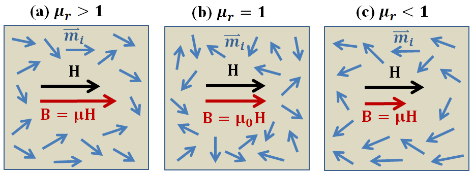
Magnetic permeability, relative increase or decrease in the resultant magnetic field inside a material compared with the magnetizing field in which the given material is......
Magnetic permeability, relative increase or decrease in the resultant magnetic field inside a material compared with the magnetizing field in which the given material is located; or the property of a material that is equal to the magnetic flux density B established within the material by a magnetizing field divided by the magnetic field strength H of the magnetizing field. Magnetic permeability μ (Greek mu) is thus defined as μ = B/H. Magnetic flux density B is a measure of the actual magnetic field within a material considered as a concentration of magnetic field lines, or flux, per unit cross-sectional area. Magnetic field strength H is a measure of the magnetizing field produced by electric current flow in a coil of wire.
In empty, or free, space the magnetic flux density is the same as the magnetizing field because there is no matter to modify the field. In centimetre–gram–second (cgs) units, the permeability B/H of space is dimensionless and has a value of 1. In metre–kilogram–second (mks) and SI units, B and H have different dimensions, and the permeability of free space (symbolized μ0) was defined as equal to 4π × 10-7 weber per ampere-metre so that the mks unit of electric current may be the same as the practical unit, the ampere. With the redefinition of the ampere in 2019, μ0 is no longer equal to 4π × 10-7 weber per ampere-metre and must be determined experimentally. (However, [μ0/4π × 10-7] is 1.00000000055, still very close to its former value.) In these systems the permeability, B/H, is called the absolute permeability μ of the medium. The relative permeability μr is then defined as the ratio μ/μ0, which is dimensionless. Thus, the relative permeability of free space, or vacuum, is 1.
Materials may be classified magnetically on the basis of their permeabilities. A diamagnetic material has a constant relative permeability slightly less than 1. When a diamagnetic material, such as bismuth, is placed in a magnetic field, the external field is partly expelled, and the magnetic flux density within it is slightly reduced. A paramagnetic material has a constant relative permeability slightly more than 1. When a paramagnetic material, such as platinum, is placed in a magnetic field, it becomes slightly magnetized in the direction of the external field. A ferromagnetic material, such as iron, does not have a constant relative permeability. As the magnetizing field increases, the relative permeability increases, reaches a maximum, and then decreases. Purified iron and many magnetic alloys have maximum relative permeabilities of 100,000 or more.