Magnetism around us - Applications

Alternators are efficient because they only provide energy when it’s needed. The alternator can come on and off as the battery needs to recharge. Because of this, your car doesn’t die when it’s running for a long time. One way to tell if an alternator is bad is if your car battery dies when it’s still running. This issue would mean that the alternator is not providing a charge to the battery. Overall, alternators are an enhanced version of a generator that can minimize the amount of power required, so there is less wasted energy. The main thing to know about an alternator is that it cannot charge a completely drained battery. This can cause fires and further damage.
In the latter case, a permanent magnet may be installed in the frame of a window or door, and a piece of magnetized material in the window or door itself. Once the alarm is activated, it will respond to any change in the magnetic field—i.e., when someone slides open the door or window, thus breaking the connection between magnet and metal. Though burglar alarms may vary in complexity, and indeed there may be much more advanced systems using microwaves or infrared rays, the application of magnetism in home security is a simple matter of responding to changes in a magnetic field. In this regard, the principle governing magnetometers used at security checkpoints is even simpler. Whether at an airport or at the entrance to some other high-security venue, whether handheld or stationary, a magnetometer merely detects the presence of magnetic metals. Since the vast majority of firearms, knife-blades, and other weapons are made of iron or steel, this provides a fairly efficient means of detection.

Electric motors may be classified by considerations such as power source type, internal construction, application and type of motion output. In addition to AC versus DC types, motors may be brushed or brushless, may be of various phase (see single-phase, two-phase, or three-phase), and may be either air-cooled or liquid-cooled. General-purpose motors with standard dimensions and characteristics provide convenient mechanical power for industrial use. The largest electric motors are used for ship propulsion, pipeline compression and pumped-storage applications with ratings reaching 100 megawatts. Electric motors are found in industrial fans, blowers and pumps, machine tools, household appliances, power tools and disk drives. Small motors may be found in electric watches.
In certain applications, such as in regenerative braking with traction motors, electric motors can be used in reverse as generators to recover energy that might otherwise be lost as heat and friction.
Electric motors produce linear or rotary force (torque) intended to propel some external mechanism, such as a fan or an elevator. An electric motor is generally designed for continuous rotation, or for linear movement over a significant distance compared to its size. Magnetic solenoids produce significant mechanical force, but over an operating distance comparable to their size. Transducers such as loudspeakers and microphones convert between electrical current and mechanical force to reproduce signals such as speech. When compared with common internal combustion engines (ICEs), electric motors are lightweight, physically smaller, provide more power output, are mechanically simpler and cheaper to build, while providing instant and consistent torque at any speed, with more responsiveness, higher overall efficiency and lower heat generation. However, electric motors are not as convenient or common as ICEs in mobile applications (i.e. cars and buses) as they require a large and expensive battery, while ICEs require a relatively small fuel tank.
Early motors
The first electric motors were simple electrostatic devices described in experiments by Scottish monk Andrew Gordon and American experimenter Benjamin Franklin in the 1740s. The theoretical principle behind them, Coulomb's law, was discovered but not published, by Henry Cavendish in 1771. This law was discovered independently by Charles-Augustin de Coulomb in 1785, who published it so that it is now known with his name.[4] The invention of the electrochemical battery by Alessandro Volta in 1799 made possible the production of persistent electric currents. After the discovery of the interaction between such a current and a magnetic field, namely the electromagnetic interaction by Hans Christian Ørsted in 1820 much progress was soon made. It only took a few weeks for André-Marie Ampère to develop the first formulation of the electromagnetic interaction and present the Ampère's force law, that described the production of mechanical force by the interaction of an electric current and a magnetic field. The first demonstration of the effect with a rotary motion was given by Michael Faraday in 1821. A free-hanging wire was dipped into a pool of mercury, on which a permanent magnet (PM) was placed. When a current was passed through the wire, the wire rotated around the magnet, showing that the current gave rise to a close circular magnetic field around the wire. This motor is often demonstrated in physics experiments, substituting brine for (toxic) mercury. Barlow's wheel was an early refinement to this Faraday demonstration, although these and similar homopolar motors remained unsuited to practical application until late in the century.
In 1827, Hungarian physicist Ányos Jedlik started experimenting with electromagnetic coils. After Jedlik solved the technical problems of continuous rotation with the invention of the commutator, he called his early devices "electromagnetic self-rotors". Although they were used only for teaching, in 1828 Jedlik demonstrated the first device to contain the three main components of practical DC motors: the stator, rotor and commutator. The device employed no permanent magnets, as the magnetic fields of both the stationary and revolving components were produced solely by the currents flowing through their windings.
Motor control
DC motors can be operated at variable speeds by adjusting the DC voltage applied to the terminals or by using pulse-width modulation (PWM).
AC motors operated at a fixed speed are generally powered directly from the grid or through motor soft starters.
AC motors operated at variable speeds are powered with various power inverter, variable-frequency drive or electronic commutator technologies.
The term electronic commutator is usually associated with self-commutated brushless DC motor and switched reluctance motor applications.
Major categories
Electric motors operate on three different physical principles: magnetism, electrostatics and piezoelectricity.
In magnetic motors, magnetic fields are formed in both the rotor and the stator. The product between these two fields gives rise to a force, and thus a torque on the motor shaft. One, or both, of these fields must be made to change with the rotation of the motor. This is done by switching the poles on and off at the right time, or varying the strength of the pole.
The main types are DC motors and AC motors,[64] the former increasingly being displaced by the latter.
AC electric motors are either asynchronous or synchronous.
Once started, a synchronous motor requires synchronism with the moving magnetic field's synchronous speed for all normal torque conditions.
In synchronous machines, the magnetic field must be provided by means other than induction such as from separately excited windings or permanent magnets.
A fractional-horsepower motor motor either has a rating below about 1 horsepower (0.746 kW), or is manufactured with a standard-frame size smaller than a standard 1 HP motor. Many household and industrial motors are in the fractional-horsepower class.
Non-magnetic motors
An electrostatic motor is based on the attraction and repulsion of electric charge. Usually, electrostatic motors are the dual of conventional coil-based motors. They typically require a high-voltage power supply, although very small motors employ lower voltages. Conventional electric motors instead employ magnetic attraction and repulsion, and require high current at low voltages. In the 1750s, the first electrostatic motors were developed by Benjamin Franklin and Andrew Gordon. Today, the electrostatic motor finds frequent use in micro-electro-mechanical systems (MEMS) where their drive voltages are below 100 volts, and where moving, charged plates are far easier to fabricate than coils and iron cores. Also, the molecular machinery that runs living cells is often based on linear and rotary electrostatic motors.
A piezoelectric motor or piezo motor is a type of electric motor based upon the change in shape of a piezoelectric material when an electric field is applied. Piezoelectric motors make use of the converse piezoelectric effect whereby the material produces acoustic or ultrasonic vibrations to produce linear or rotary motion. In one mechanism, the elongation in a single plane is used to make a series of stretches and position holds, similar to the way a caterpillar moves.
An electrically powered spacecraft propulsion system uses electric motor technology to propel spacecraft in outer space, most systems being based on electrically powering propellant to high speed, with some systems being based on electrodynamic tethers principles of propulsion to the magnetosphere.
The engineering design of electromagnets is systematized by means of the concept of the magnetic circuit. In the magnetic circuit a magnetomotive force F, or Fm, is defined as the ampere-turns of the coil that generates the magnetic field to produce the magnetic flux in the circuit. Thus, if a coil of n turns per metre carries a current i amperes, the field inside the coil is ni amperes per metre and the magnetomotive force that it generates is nil ampere-turns, where l is the length of the coil. More conveniently, the magnetomotive force is Ni, where N is the total number of turns in the coil. The magnetic flux density B is the equivalent, in the magnetic circuit, of the current density in an electric circuit. In the magnetic circuit the magnetic equivalent to current is the total flux symbolized by the Greek letter phi, ϕ, given by BA, where A is the cross-sectional area of the magnetic circuit. In an electric circuit the electromotive force (E) is related to the current, i, in the circuit by E = Ri, where R is the resistance of the circuit. In the magnetic circuit F = rϕ, where r is the reluctance of the magnetic circuit and is equivalent to resistance in the electric circuit. Reluctance is obtained by dividing the length of the magnetic path l by the permeability times the cross-sectional area A; thus r = l/μA, the Greek letter mu, μ, symbolizing the permeability of the medium forming the magnetic circuit. The units of reluctance are ampere-turns per weber. These concepts can be employed to calculate the reluctance of a magnetic circuit and thus the current required through a coil to force the desired flux through this circuit.
Several assumptions involved in this type of calculation, however, make it at best only an approximate guide to design. The effect of a permeable medium on a magnetic field can be visualized as being to crowd the magnetic lines of force into itself. Conversely, the lines of force passing from a region of high to one of low permeability tend to spread out, and this occurrence will take place at an air gap. Thus the flux density, which is proportional to the number of lines of force per unit area, will be reduced in the air gap by the lines bulging out, or fringing, at the sides of the gap. This effect will increase for longer gaps; rough corrections can be made for taking the fringing effect into account.
It has also been assumed that the magnetic field is entirely confined within the coil. In fact, there is always a certain amount of leakage flux, represented by magnetic lines of force around the outside of the coil, which does not contribute to the magnetization of the core. The leakage flux is generally small if the permeability of the magnetic core is relatively high.
In practice, the permeability of a magnetic material is a function of the flux density in it. Thus, the calculation can only be done for a real material if the actual magnetization curve, or, more usefully, a graph of μ against B, is available.
Finally, the design assumes that the magnetic core is not magnetized to saturation. If it were, the flux density could not be increased in the air gap in this design, no matter how much current were passed through the coil. These concepts are expanded further in following sections on specific devices.
Design Of Large Electromagnets.
Sooner or later almost every scientific research laboratory finds that it requires a facility for producing large magnetic fields. A number of advanced technologies likewise require large electromagnets. A cyclotron, for example, is a device used for scientific research in which subatomic charged particles are accelerated by an alternating electric field in a constant magnetic field. It uses a large magnet to produce moderate fields but with a pole diameter that may be several metres. Some industries make use of huge, high-powered electromagnets for lifting purposes.
The basic design principles of large electromagnets are those discussed earlier. The difficulties arise in trying to estimate the magnitude of the fringing flux across the air gap and the leakage flux around the coils. Their effects are minimized by using a tapered shape for the cores and pole caps; a typical laboratory magnet is shown in Figure 4. Because soft iron saturates at 2.16 webers per square m, flux densities in the air gap are generally limited to the region of 2.1 webers per square m with iron magnets.
When designed for lifting or load-carrying purposes, an electromagnet may be required to have a single exposed pole face to which the load to be carried will attach itself, and it will therefore have the shape of a bar magnet. The design is then dominated by the demagnetizing field. Suitably designed magnets can lift many times their own weight and are in general use in steelworks and scrapyards.

An electromagnetic crane is a type of crane in which we are using an electromagnet (which is made up of soft iron core and a copper wire is wounded around its periphery) to lift the heavy metal (made up of ferrous metal) and thus the work piece is lifted and keep in desired place by electromagnetic crane.
MECHANISM OF ELECTROMAGNETIC CRANE
The magnetic strength of an electromagnet depends on the number of turns or wire and the current through the wire, and the size of the iron core. This allows electromagnets to be made much larger and stronger than a natural magnet, such that they can pick up very large objects. Also, when you turn off the electricity to an electromagnet, the magnetism is also turned off. Thus, an electromagnet can be used to pick up a piece of iron and then drop it some place else.
History of crane
The first construction cranes were invented by the Ancient Greeks and were powered by men or beasts of burden, such as donkeys. Larger cranes were later developed, employing the use of human tread wheels, permitting the lifting of heavier weights. Use of crane Cranes are commonly employed in the transport industry for the loading and unloading of freight, in the construction industry for the movement of materials and in the manufacturing industry for the assembling of heavy equipment. The first construction cranes were invented by the Ancient Greeks and were powered by men or beasts of burden, such as donkeys. These cranes were used for the construction of tall buildings. Larger cranes were later developed, employing the use of human treadwheels, permitting the lifting of heavier weights.
Evolution of crane
The earliest cranes were constructed from wood, but cast iron and steel took over with the coming of the Industrial Revolution. For many centuries, power was supplied by the physical exertion of men or animals, although hoists in watermills and windmills could be driven by the harnessed natural power. The first 'mechanical' power was provided by steam engines, the earliest steamcrane being introduced in the 18th or 19th century, with many remaining in use well into the late 20th century. Mini - cranes are also used for constructing high buildings, in order to facilitate constructions by reaching tight spaces. Finally, we can find larger floating cranes, generally used to build oil rigs and salvage sunken ships. we can find larger floating cranes, generally used to build oil rigs and salvage sunken ships. The article also covers lifting machines that do not strictly fit the above definition of a crane, but are generally known as cranes, such as stacker cranes and loader cranes. There are used motors to move the craned."

Hence, the magnetic field of an alternator is always rotating inside the stator, whereas, the magnetic field for a generator is fixed. The armature is the rotating coil or series of coils in an electric motor. When the armature is stationary it becomes easy to produce voltage(low voltage) excitation to the rotor through the slip rings. You would choose a generator when more electricity is needed because they produce voltage throughout the entire device without stopping. You can use a generator to charge a battery when it’s completely drained as well. For this reason, we see generators as the best possible option as a power backup for homes and RVs. These are cut out for the big jobs because the output current is constant, and it generates both Alternating current and Direct Current.
Hall probe
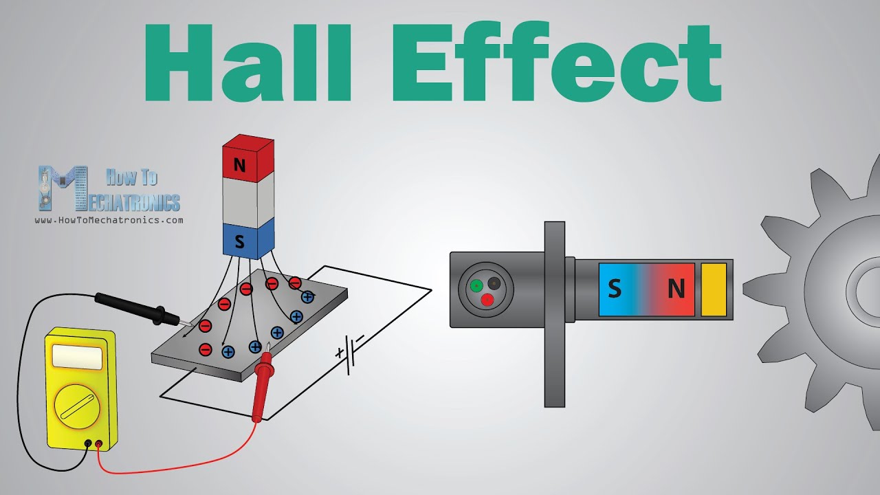
A Hall probe contains an indium-compound semiconductor crystal such as indium antimonide, mounted on an aluminum backing plate and encapsulated in the probe head. The plane of the crystal is perpendicular to the probe handle. Connecting leads from the crystal are brought down through the handle to the circuit box. When the Hall probe is held so that the magnetic field lines are passing at right angles through the sensor of the probe, the meter gives a reading of the value of magnetic flux density (B). A current is passed through the crystal, which, when placed in a magnetic field, has a "Hall effect" voltage developed across it. The Hall effect is seen when a conductor is passed through a uniform magnetic field. The natural electron drift of the charge carriers causes the magnetic field to apply a Lorentz force (the force exerted on a charged particle in an electromagnetic field) to these charge carriers, resulting in charge separation, with a buildup of either positive or negative charges on the bottom or on the top of the plate. The crystal measures 5 mm square. The probe handle, being made of a non-ferrous material, has no disturbing effect on the field. A Hall probe should be calibrated against a known value of magnetic field strength. For a solenoid the Hall probe is placed in the centre.
Working principle
In a Hall-effect sensor, a thin strip of metal has a current applied along it. In the presence of a magnetic field, the electrons in the metal strip are deflected toward one edge, producing a voltage gradient across the short side of the strip (perpendicular to the feed current). Hall-effect sensors have an advantage over inductive sensors in that, while inductive sensors respond to a changing magnetic field that induces current in a coil of wire and produces voltage at its output, Hall-effect sensors can detect static (non-changing) magnetic fields.
In its simplest form, the sensor operates as an analog transducer, directly returning a voltage. With a known magnetic field, its distance from the Hall plate can be determined. Using groups of sensors, the relative position of the magnet can be deduced.
When a beam of charged particles passes through a magnetic field, forces act on the particles, and the beam is deflected from a straight path. The flow of electrons through a conductor forms a beam of charged carriers. When a conductor is placed in a magnetic field perpendicular to the direction of the electrons, they are deflected from a straight path. As a consequence, one plane of the conductor becomes negatively charged, and the opposite side becomes positively charged. The voltage between these planes is called the Hall voltage.
When the force on the charged particles from the electric field balances the force produced by the magnetic field, the separation of charges stops. If the current is not changing, then the Hall voltage is a measure of the magnetic flux density. Basically, there are two kinds of Hall-effect sensors: linear, which means that the output of voltage linearly depends on magnetic flux density; and threshold, which means that there is a sharp decrease of output voltage at some magnetic flux density. This experiment was the one to demonstrate that there are only negative charges free to move in a conductor. Before this, it was believed that positive charges move in a current-carrying conductor. This experiment is known as the Hall experiment.
Materials
The key factor determining sensitivity of Hall-effect sensors is high electron mobility. As a result, the following materials are especially suitable for Hall-effect sensors:
gallium arsenide (GaAs),
indium arsenide (InAs),
indium phosphide (InP),
indium antimonide (InSb),
graphene.
Advantages
A Hall-effect sensor may operate as an electronic switch.
Such a switch costs less than a mechanical switch and is much more reliable.
It can be operated at higher frequencies than a mechanical switch.
It does not suffer from contact bounce because a solid-state switch with hysteresis is used rather than a mechanical contact.
It is not affected by environmental contaminants, since the sensor is in a sealed package. Therefore, it can be used under severe conditions.
In the case of linear sensor (for the magnetic-field-strength measurements), a Hall-effect sensor:
can measure a wide range of magnetic fields,
can measure both sign and amplitude,
can be flat.
Disadvantages
Hall-effect sensors provide much lower measuring accuracy than fluxgate magnetometers or magnetoresistance-based sensors. Moreover, Hall-effect sensors drift significantly, requiring compensation.

An electromagnet is just a coil of wires with a current running through it. Electrons are like tiny magnets and when they move (as in a current), they create a magnetic field. The iron core increases the magnetic field of the electromagnet. The ring feels a greater magnetic force, which pushes it higher. The colder the ring it, the less resistance there is and the more current can flow through it. More current means a bigger magnetic field and the ring goes even higher!
The Details:
The jumping ring makes a metal ring jump up into the air using an electromagnet like the one described earlier. It is actually two electromagnets in one. Wire is wrapped around a base made of iron. The wire is connected to the electricity and when current flows in the wire, the iron becomes a very strong magnet. The second magnet is a metal ring. It sits on top of the iron base. The magnetic field from the iron in the base causes electricity to flow around through the ring. The electricity in the ring is called an eddy current. The eddy current causes the metal ring to become a magnet. The two electromagnets are arranged so that their north poles point at each other. Two north poles repel each other, so the base and the ring push each other away. Since the ring is very light, it gets pushed up into the air.
When you add an additional iron bar into the electromagnet, it increases its strength. (This is why we used a nail in the previous electromagnet experiment.) A stronger magnet makes the ring jump much higher! If you add a second ring, you might expect it not to go as high because there is twice as much mass. But, there is also twice as much ring to turn into a magnet that will be repelled and it launches just as high.
We can make the ring jump much higher by using liquid nitrogen to make it very cold. When things are very cold, electricity can flow more easily. Since the electricity can flow through the ring better, the ring becomes a stronger magnet and jumps a lot higher.
If the ring gets cut, it won’t jump. We said some of the electricity in the wire gets into the ring to make it into a magnet. But, electricity has to flow in a complete circle to make a magnet. Since there is a cut, the electricity can’t get all the way around. The cut keeps the ring from turning into a magnet.

The dynamic speaker was invented in 1924 by Edward W. Kellogg and Chester W. Rice. The dynamic speaker operates on the same basic principle as a dynamic microphone, but in reverse, to produce sound from an electrical signal. When an alternating current electrical audio signal is applied to its voice coil, a coil of wire suspended in a circular gap between the poles of a permanent magnet, the coil is forced to move rapidly back and forth due to Faraday's law of induction, which causes a diaphragm (usually conically shaped) attached to the coil to move back and forth, pushing on the air to create sound waves. Besides this most common method, there are several alternative technologies that can be used to convert an electrical signal into sound. Speakers are typically housed in a speaker enclosure or speaker cabinet which is often a rectangular box made of wood or sometimes plastic. The enclosure's materials and design play an important role in the quality of the sound. The enclosure generally must be as stiff and non-resonant as practically possible. Where high fidelity reproduction of sound is required, multiple loudspeaker transducers are often mounted in the same enclosure, each reproducing a part of the audible frequency range (picture at right). In this case, the individual speakers are referred to as drivers and the entire unit is called a loudspeaker. Drivers made for reproducing high audio frequencies are called tweeters, those for middle frequencies are called mid-range drivers and those for low frequencies are called woofers. Extremely low frequencies (16Hz-~100Hz) may be reproduced by separate subwoofers. Smaller loudspeakers are found in devices such as radios, televisions, portable audio players, computers, and electronic musical instruments. Larger loudspeaker systems are used for music, sound reinforcement in theatres and concert halls, and in public address systems.