Magnetism around us - Materials
Aluminium (Al), Nickel (Ni) and Cobalt Alloys (AlNiCo)
Alnico is now a generic name for a family of alloys, known by several trade names, containing substantial amounts of all three of the ferromagnetic metals, Fe, Co, and Ni, plus smaller amounts of Al, Cu, and sometimes other elements. The name comes from the chemical symbols for aluminum, nickel, and cobalt, even though all alnicos have iron as a major constituent. They were at one time the most widely used permanent magnet materials, but have now been largely replaced by permanent magnet ferrites and rare earth-transition metal alloys. Alnicos have relatively high Curie temperatures and therefore relatively small temperature dependence of magnetic properties near room temperature, which is a major advantage in some applications.
The development of alnico dates from 1931, when Mishima in Japan discovered that an alloy of 58% Fe, 30% Ni, and 12% Al had a coercivity of over 400 Oe, nearly double that of the best magnet steel. It was soon discovered that the addition of Co and Cu improved the properties of the Mishima alloy, and many related alloys have been tested and manufactured.
Producers of alnico and other permanent magnet materials do not usually specify the compositions of their alloys, but only their magnetic properties. The alnicos are not steels. They are essentially carbon-free, do not form or contain martensite, and the mechanism of their magnetic hardness is quite different from that of steel.
Article src: Introduction to Magnetic Materials (2nd Edition), B. D. Cullity, C. D. Graham, Wiley-IEEE Press, 2008.
Hard Ferrites

Img src
These materials, also known as ceramic magnets, were developed in the 1950s as a result of the Stoner-Wohlfarth theory which indicated that the coercivity of a system of single-domain particles was proportional to the anisotropy. The theory thus provided a direction for the permanent magnet industry by indicating the types of materials which should prove to be good permanent magnets. This led the permanent magnet manufacturers to try to develop highly anisotropic materials in the form of aggregations of single-domain particles. The cause of the anisotropy could be either crystalline or small-particle shape effects.
However, it has been found that the coercivities of real materials have always been much smaller than the theoretical predictions of Stoner and Wohlfarth since mechanisms other than coherent domain rotation are almost always available and these can take place at lower coercivities.
The hard hexagonal ferrites in widespread use are usually either barium or strontium ferrite (BaO·6Fe203 or SrO·6Fe203). These materials are relatively cheap to produce and commercially remain the most important of the permanent.
Article src: Introduction to Magnetism and Magnetic Materials (1nd edition), David Jiles, Chapman & Hall/CRC, 1991.
Iron Cobalt Alloys
The high saturation of iron-cobalt alloys was first noted by Preuss (1912) and also by Weiss (1912) on the alloy Fe2Co. The 50% Co alloy with a higher permeability and only a slightly lower saturation was reported by Ellis (1927) but had been patented by Elman (1929 a year earlier. The name Permendur was applied to this alloy because the permeability endured even at high saturations. In 1932, White and Wahl (1932) patented a modification of this alloy which added vanadium to it to make it easier to cold work. Later, Gould and Wenny (1957) refined the process by using high purity materials and special processing. They called the material Supermendur.
Article src: Handbook of modern ferromagnetic materials, A. Goldman, B.S., Springer Science+Business Media New York, Ferrite Technology Worldwide, (1st edition), 1999.
Iron Silicon Alloys
Img src
In electrical power generation and transmission the greatest demand is for transformer cores. In this area silicon-iron is used to the exclusion of all others. This is also known as 'electrical steel' or silicon steel both of which are misnomers since these materials are not really steels.
In the power industry the electrical voltage is almost always low-frequency a.c. at 50 or 60 Hz. This leads to an alternating flux in the cores of the electromagnetic devices and consequently to the generation of 'eddy currents' if the material is an electrical conductor. Eddy currents reduce the efficiency of transformers because some of the energy is lost through eddy current dissipation.
There are several ways in which the properties of pure iron can be improved in order to make it more suitable for transformer cores at low frequencies. First the resistivity can be increased so that the eddy current losses become less. This is achieved by the alloying of silicon with iron. Iron containing 3% silicon has four times the resistivity of pure iron. Over the years there have been substantial improvements in the core losses of silicon iron.
Silicon of course is a very cheap material which is an important consideration when so much transformer iron is needed. It has two main beneficial effects on the properties of the alloy. The conductivity is reduced as silicon is added and the magnetostriction is reduced. For a.c. applications this reduction of magnetostriction is an additional advantage since the cyclic stresses resulting from magnetostrictive strains at 50 or 60 Hz produce acoustic noise.
Therefore any reduction of magnetostriction is desirable, particularly if it arises as a result of modifying the material to suit other unrelated requirements. A third benefit caused by the addition of silicon is that it reduces the anisotropy of the alloy leading to an increase in permeability in the non-oriented silicon-iron.
It is also beneficial to laminate the cores in such a way that the laminations run parallel to the magnetic field direction. This does not interfere with the magnetic flux path but does reduce the eddy current losses, by only allowing the eddy currents to exist in a narrow layer of material. The dependence of core losses at 60 Hz on sheet thickness is shown in Figure. Furthermore the coating of laminations with an insulating material also improves the eddy current losses by preventing current passing from one layer to the next. The thickness of the laminations is comparable with the skin depth at 50 or 60 Hz, which is typically 0.3-0.7mm, for optimum performance.
There are nevertheless some disadvantages involved with the addition of silicon to iron. At higher silicon contents the alloy becomes very brittle and this makes a practical limitation on the level of silicon that can be added without the material becoming too brittle to use. This limit is about 4% and most silicon-iron transformer material has a composition of 3-4% Si, although material with a silicon content of 6% with adequate mechanical properties for transformer applications has recently been developed. Another disadvantage resulting from the addition of silicon to iron is the reduction of saturation induction.
Article src: Introduction to Magnetism and Magnetic Materials (1nd edition), David Jiles, Chapman & Hall/CRC, 1991.
Low-Carbon Steels
These were the original materials for transformers, motors and generators but have been superseded by silicon-iron both in its oriented form for transformers and in its non-oriented form for motors and generators.
Soft iron is used as a core material for d.c. electromagnets such as laboratory electromagnets for which it remains the best material. The prime concern is merely to obtain either high fields and or very uniform magnetic fields. Iron with low levels of impurities such as carbon (0.05%) and nitrogen has a coercivity of about 80 A/m (1 Oe) and a maximum relative permeability of the order of 10000. By annealing in hydrogen the impurities can be removed and this results in a reduction in coercivity to 4A/m (0.05 Oe) and an increase in maximum relative permeability to about 100000. The highest relative permeability obtained for pure iron is 1.5 x 10⁶, however the problem with this from a commercial viewpoint is that it is too expensive for many applications.
Article src: Introduction to Magnetism and Magnetic Materials (1nd edition), David Jiles, Chapman & Hall/CRC, 1991.
Magnet Steels
We turn now to the magnet materials themselves. The earliest of these was the lodestone, sometimes “armed” by attaching soft iron at each end to concentrate the flux. This is the origin of the term “armature” for a part of a magnetic circuit. Next came high-carbon steel magnets, hardened by quenching (rapid cooling from high temperature), which were used for centuries as compass needles.
In the later 1800s, alloy steels were developed for cutting tools and for structural purposes, and the magnetic properties of alloy steels became of interest. By 1885 a steel containing about 5% tungsten was in use for magnets. This was supplanted by the cheaper chromium steel during World War I. Neither type had coercivity as much as 100 Oe (8 kA/m). The next advance was made in 1917 by the Japanese investigators Honda and Takagi, who showed that a steel containing 30–40% cobalt, plus tungsten and chromium, had a coercivity of 230 Oe. This is still the best magnet steel; it has an energy product approaching 1MGOe or 8 kJ/m3.
Steel magnets always contain carbon, and are used in the hardened state; that is, they are quenched to produce the metastable tetragonal martensitic structure. In steels, magnetic hardness (high coercivity) accompanies physical hardness, although this is emphatically not true of magnetic materials generally. The origin of the magnetic hardness of steels, such as it is, is something of a mystery. Isolated single crystals of martensite are unobtainable, so its magnetic anisotropy is unknown. A martensitic steel is in a complex state of internal stress, and metal carbide particles may also be present; presumably both of these make domain wall motion difficult.
Magnet steels are no longer made or used, since much better materials are available. The cheapest magnet steels have very poor permanent magnetic properties, and the best ones are relatively expensive because of their high cobalt content.
Article src: Introduction to Magnetism and Magnetic Materials (1nd edition), David Jiles, Chapman & Hall/CRC, 1991.
Neodymium Iron Boron (FeNdB)
Efforts to find better and/or cheaper permanent magnet materials led to two essentially simultaneous discoveries of Fe14Nd2B, a previously unknown tetragonal crystal with strong uniaxial anisotropy and a Curie temperature slightly above 300oC. Magnets made using methods very similar to those used for SmCo5 were announced by Sumitomo Special Metals Co, in Japan in 1984. At almost the same time, magnets of approximately the same composition but made by a rapid solidification technique, like that used for amorphous alloys, were announced by General Motors Corp. Extensive and complicated patent disputes ensued, but both products are in large-scale commercial production, and have to a large extent replaced the Sm–Co materials, because FeNdB is cheaper. Fe is cheaper than Co, Nd is cheaper than Sm, and FeNdB contains relatively little rare earth.
As noted above, conventional FeNdB is made using the same processes and equipment as Sm–Co, which helped to makes its adoption quite rapid. Some of the Fe may be replaced with Co, which increases the Curie temperature and improves the temperature stability. Some of the Nd may be replaced with a heavy rare earth, usually dysprosium, which increases coercivity, but lowers magnetization. Often both are added. FeNdB magnets are available in a range of magnetic properties, with energy products from 20 to 40 MGOe, and magnets have been made with energy products of 50 MGOe or more. (Multiply these values by 7.96 to get SI units of kJ/m3.) They are the materials of choice when small size is important, as in many computer-related devices.
Rapidly quenched FeNdB is produced in a partially amorphous state, and annealed to produce a very fine-grained crystalline material. This is ground into a coarse flake, which can be hot-pressed to full density. Since each flake contains many grains, oriented at random, magnets made in this way are unoriented, with isotropic magnetic properties. It is possible to align the easy axes by a process of hot deformation known as die-upsetting. A cylindrical sample is placed in a die whose inside diameter is about twice the sample diameter, and the sample is compressed at a temperature of about 725oC to fill the die. After this treatment the easy axes are predominantly aligned parallel to the compression axis.
Article src: Introduction to Magnetic Materials (2nd Edition), B. D. Cullity, C. D. Graham, Wiley-IEEE Press, 2008.
Permalloys
Img src
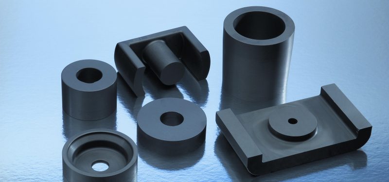
These are mainly nickel–iron alloys containing either about 50 or 80% Ni, known generically as permalloys. This is a former trade name, but is now used for any Ni–Fe alloy. If a number precedes the name (79 permalloy), it denotes the Ni content. The permalloys have high permeability in low fields and low losses, and can be rolled to very small thicknesses.
They are the materials of choice when excellent magnetic properties are required, and cost is not the primary consideration. The alloys were developed as commercial materials for use in the telephone system, mainly in the period 1913–1921, and are described fully in Bozorth’s book Ferromagnetism. There has been relatively little change or improvement in these materials for the last 50 years, although better manufacturing methods have increased purity and permeability to some degree. Permalloys are made and sold under a variety of trade names.
In the range of 50–80% Ni the alloys are all face-centered cubic. At and near the composition FeNi3 the alloys can undergo long-range ordering below a temperature of 503oC. The magnetic properties of the ordered alloys are inferior to those of the disordered. The disorder-to-order transformation is fortunately sluggish and can be avoided simply by fairly rapid cooling through the 500–400oC range; water quenching is unnecessary.
The variation of saturation magnetization and Curie temperature with composition is shown in Figure. Alloys near 30% Ni contain two phases, bcc a and fcc g. The phase mixture, and the resulting magnetic and other properties, depend very strongly on the composition, impurity level, and thermal history of the sample. Figure also shows the variation of the magnetocrystalline anisotropy, and K1 is seen to pass through zero at about 75% Ni.
Article src: Introduction to Magnetic Materials (2nd Edition), B. D. Cullity, C. D. Graham, Wiley-IEEE Press, 2008.
Platinum-Cobalt (Pt-Co)
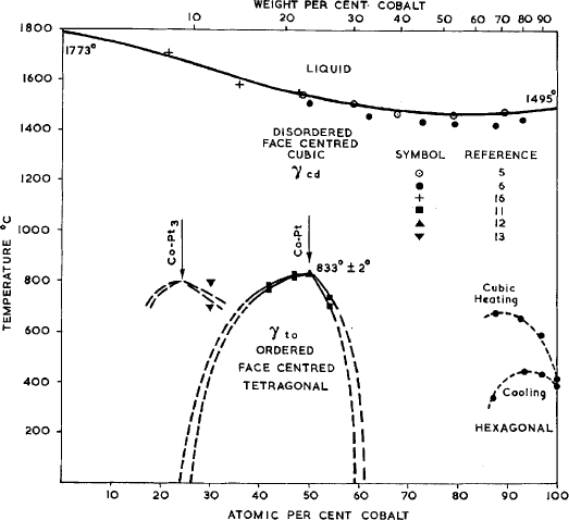
Another exotic alloy using very costly raw materials is platinum-cobalt. The energy product is quite high at 5.5 MGO but its cost is so prohibitive that, with the availability of the new high-energy materials to be described next, their production has all but disappeared. The platinum-cobalt material has been known for some time and has good properties but its cost is prohibitive.
The equiatomic alloy CoPt is the most expensive magnetic material ever made commercially. Like the alloys listed above, when heat treated to produce a single-phase solid solution, it is ductile. It is then heat treated to develop a two-phase, partially ordered structure, which can have an energy product approaching 10 MGOe. Until the development of the rare-earth permanent magnets, CoPt was the best permanent magnet available, and was used in miniature devices such as hearing aids and watches, and in some military and space applications where cost was not a major consideration. It now has only a few special-purpose uses, some due to its good corrosion resistance.
Article src: Handbook of modern ferromagnetic materials, A. Goldman, B.S., Springer Science+Business Media New York, Ferrite Technology Worldwide, (1st edition), 1999.
Article src: Introduction to Magnetic Materials (2nd Edition), B. D. Cullity, C. D. Graham, Wiley-IEEE Press, 2008.
Samarium Cobalt (SmCo5)
This compound has a hexagonal crystal structure, and an anisotropy constant of about 7.7 x 10⁷ erg/cm3 or 7.7 x 10⁶ J/m3, with the easy axis along the c-axis of the unit cell. The basic production method consists of melting and casting the alloy, crushing and grinding to produce a powder with particle size near 10 mm, and with each particle consisting of a single crystal of SmCo5. The powder is aligned in a magnetic field so that the easy axes of all the particles are parallel, and then compressed in a die. Usually the alignment and compression are done sequentially in the same apparatus. The compressed powder is then sintered at a temperature above 1000oC to make a final magnet.
To obtain high density and good magnetic properties, a small amount of powder made with an excess Sm content is added before compaction. This material melts at the sintering temperature, and greatly aides in attaining high density. The process is referred to as liquid phase sintering. The particle size of the powder before sintering corresponds to the grain size after sintering, and is about an order or magnitude larger than the calculated size of single-domain particles. So these are not in fact single-domain particle magnets, although they were originally developed on the basis of single-domain theory.
Article src: Introduction to Magnetic Materials (2nd Edition), B. D. Cullity, C. D. Graham, Wiley-IEEE Press, 2008.
Soft Ferrites
Ferrites are a family of ferrimagnets. They are a group of compounds with the chemical formula MO-Fe2O3 where M is a divalent cation such as Zn2+ , Co2+ , Fe2+ , Ni2+ , Cu2+ or Mn2+. The crystal structure is the spinel structure which contains two types of lattice sites, tetrahedral sites (with four oxygen neighbours, these are known as A sites) and octahedral sites (with six oxygen neighbours, these are known as B sites). There are twice as many B sites as A sites. The two sublattices are non-equivalent because there are two types of crystallographic site and they contain two types of different ion. In normal spinels, the M2+ cations sit at the A sites and the Fe3+ (6 S 5/2 and therefore a moment of 5 μB) cations sit at the B sites. In inverse spinels the M2+ cations sit at half of the B sites, while the Fe3+ cations occupy the other half of the B sites and all the A sites. In inverse spinels, the moments of the Fe3+ cations on the A and the B sites are antiparallel, so that the total moment of the sample is due to the M2+ ions only.
The case of M=Fe, i.e. Fe3O4 (which is a semiconductor, in contrast to the other ferrites which are insulators). Another family of ferrimagnets is the garnets which have the chemical formula R3Fe5O12 where R is a trivalent rare earth atom. The crystal structure is cubic, but the unit cell is quite complex. Three of the Fe3+ ions are on tetrahedral sites, two are on octahedral sites and the R3+ ions are on sites of dodecahedral symmetry. In yttrium iron garnet (YIG), Y3Fe5O12, the Y3+ has no magnetic moment (it is 4d°) and the moments of the Fe3+ ions on the tetrahedral sites are antiparallel to those on the octahedral sites, so that the net moment is 5μB.
Barium ferrite (BaFe12O19 = BaO.6Fe2O3) has a hexagonal structure. Eight of the Fe3+ ions are antiparallel to the other four, so that the net moment is equivalent to four Fe3+ ions, i.e. 20μB. In powder form, it is used in magnetic recording since it has a high coercivity.
Most ferrimagnets are electrical insulators and this fact is responsible for many of their practical applications. Ferromagnets are often metallic and thus are unsuitable in applications in which an oscillating magnetic field is involved; a rapidly changing magnetic field induces a voltage and causes currents (known as eddy currents) to flow in conductors. These currents cause resistive heating in a metal (eddy current losses). Many ferrimagnets therefore can be used when a material with a spontaneous magnetization is required to operate at high frequencies, since the induced voltage will not be able to cause any significant eddy currents to flow in an insulator. Solid ferrite cores are used in many high frequency applications including aerials and transformers requiring high permeability and low energy loss, as well as applications in microwave components. Also many ferrimagnets are more corrosion resistant than metallic ferromagnets since they are already oxides.
Ferrites are made in the following way:
- Starting Material. Ferric oxide Fe2O3 and whatever oxides MO are required, in powder form. Metal carbonates may also be used; during the later firing, CO2 will be given off and they will be converted to oxides.
- Grinding. Prolonged wet grinding of the powder mixture in steel ball mills produces good mixing and a smaller particle size, which in turn decreases the porosity of the final product. After grinding, the water is removed in a filter press, and the ferrite is loosely pressed into blocks and dried.
- Presintering. This is done in air, and the temperature goes up to about 1000oC and down to 200oC in about 20 h. In this step at least partial formation of the ferrite takes place: MO- Fe2O3. This step produces a more uniform final product and reduces the shrinkage that occurs during final sintering.
- Grinding. The material is ground again to promote mixing of any unreacted oxides and to reduce the particle size.
- Pressing or Extrusion. The dry powder is mixed with an organic binder and formed into its final shape. Most shapes, such as toroidal cores, are pressed (at 1–10 ton/in2, 14–140 MPa), but rods and tubes are extruded.
- Sintering. This is the final and critical step. The heating and cooling cycle typically extends over 8 h or more, during which the temperature reaches 1200–1400oC. Any unreacted oxides form ferrite, interdiffusion occurs between adjacent particles so that they stick (sinter) together, and porosity is reduced by the diffusion of vacancies to the surface of the part. Strict control of the furnace temperature and atmosphere is very important, because these variables have marked effects on the magnetic properties of the product.
Article src: Magnetism in condensed Matter, Stephen Blundell, Oxford Master Series in Condensed Matter Physics, OXFORD University Press, 2001.
Article src: Introduction to Magnetic Materials (2nd Edition), B. D. Cullity, C. D. Graham, Wiley-IEEE Press, 2008.
Soft Iron

Img src
Pure iron is quite an attractive material because of its high saturation and low cost. It enjoys the last advantage because of its large commercial use in many other nonmagnetic applications and its ready availability.
Soft iron can be introduced into a permanent magnet circuit, either to provide a cheap return path for the flux or to concentrate the flux in the airgap, thereby creating a larger field in a smaller volume. The extra flux density can never exceed the polarization of the soft material (e.g. 2.15 T for iron or 2.45 T for permendur), and will normally be only a fraction of that.
The most important d.c. uses which soft magnetic materials find are in electromagnets and relays. An electromagnet is any device in which a magnetic field H is generated by an electric current and the resulting flux density B is increased by the use of a high-permeability core. The simplest example is a solenoid carrying a d.c. current wound around a ferromagnetic core. In electromagnets soft iron is still the most widely used material because it is relatively cheap and can produce high magnetic flux densities. It is often alloyed with a small amount of carbon ( < 0.02 wt%) without seriously impairing its magnetic properties for this application. Also the alloy Fe-35%Co is used in electromagnet pole tips to increase the saturation magnetization.
A relay is a special form of d.c. electromagnet with a moving armature which operates a switch. This can be used for example to open and close electrical circuits and is therefore important as a control device.
Article src: Magnetism and Magnetic Materials, J. M. D Coey, Cambridge University Press, 2010.
Article src: Handbook of modern ferromagnetic materials, A. Goldman, B.S., Springer Science+Business Media New York, Ferrite Technology Worldwide, (1st edition), 1999.
