Zoom to microworld - Effects
Domain wall motion
Img src
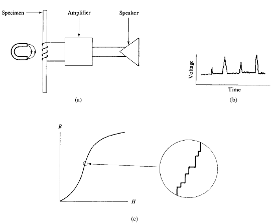
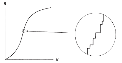
Up to this point our attention has been focused on static domain structures. We now consider how domain walls move in response to an applied field. This motion is often observed to be jerky and discontinuous, rather than smooth. This phenomenon, known as the Barkhausen effect, was discovered in 1919. A search coil is wound on a specimen and connected through an amplifier to a loudspeaker or headphones. The specimen is then subjected to a smoothly increasing field. No matter how smoothly and continuously the field is increased, a crackling noise is heard from the speaker. If the search coil is connected to an oscilloscope, instead of a speaker, irregular spikes will be observed on the voltage-time curve. These voltage spikes are known as Barkhausen noise. The emf induced in the search coil is, proportional to the rate of change of flux through it, or to dB/dt. But even when dH/dt is constant, and even on those portions of the B,H curve which are practically linear, the induced voltage is not constant with time but shows many discontinuous changes. The effect is strongest on the steepest part of the magnetization curve and is evidence for sudden, discontinuous changes in magnetization.
The Barkhausen effect was originally thought to be due to sudden rotations of the Ms vector from one orientation to another in various small volumes of the specimen. It is now known to be due mainly to domain walls making sudden jumps from one position to another. Either way, the Barkhausen effect is evidence for the existence of domains, and it was the first evidence in support of Weiss’ hypothesis of 13 years earlier. In a classic paper published in 1949, H. J. Williams and W. Shockley reported direct visual evidence of jerky domain wall motion. They made a single crystal of Fe + 3.8% Si in the form of a hollow rectangle with each side parallel to an easy direction of the form <100> and all faces parallel to {100}.
The overall dimensions were 19 x 13 mm, and each side was 1 mm wide and 0.7 mm thick. They examined the whole surface of the polished crystal by the Bitter technique and found the particularly simple domain structure. This shows the demagnetized state, and the crystal contains only eight domains. The domain walls, shown as dashed lines, were found, by observation of the other side, to pass straight through the crystal normal to the plane of the drawing. A magnetizing coil was wound on one leg and a flux-measuring coil on the opposite leg of the sample, marked in the figure as the H and B coils, respectively. When the applied field H was clockwise, the domain wall in each leg moved outward until it reached the edge of the specimen at saturation; each leg of the crystal was then a single domain. While the wall AB, for example, was moving, it could be observed with a microscope focused on the top leg.
The wall motion was generally fairly smooth, but now and then jerky when the wall encountered an inclusion.
Article src: Introduction to Magnetic Materials (2nd Edition), B. D. Cullity, C. D. Graham, Wiley-IEEE Press, 2008.
Domain walls in thin films
Img src
Except in special cases, the magnetization in thin films lies in the plane of the film, because a huge demagnetizing field would act normal to the plane of the film if Ms were turned in that direction. Domains in the film extend completely through the film thickness, and the walls between them are mainly of the 180o kind, roughly parallel to the easy axis of the film.
However, two new kinds of domain walls can exist in thin films. The first is the Neel wall, first suggested on theoretical grounds by Neel. Ordinary walls such as those found in bulk materials can also exist in thin films; they are then specifically called Bloch walls to distinguish them from Neel walls.
One does not expect a polycrystalline specimen to be a single domain in zero field. It would normally break up into domains arranged in conformity with the easy-axis direction in each grain. A thin film of 80 permalloy, however, if saturated in the easy direction, can remain a single domain after the saturating field is removed. The reason is that the demagnetizing field in the plane of the film is nearly zero, because the film is so thin. In addition, the grain size is very small. If each grain became a domain, large numbers of free poles would form at grain boundaries, and the magnetostatic energy would be high.
Article src: Introduction to Magnetic Materials (2nd Edition), B. D. Cullity, C. D. Graham, Wiley-IEEE Press, 2008.
Domain-wall pinning
The inclusion theory of domain-wall pinning was suggested by Kersten. He assumed that the magnetic domain walls move in a planar manner through the solid and that the energy of the walls is reduced when they intersect inclusions. The inclusions themselves may take many forms such as insoluble second-phase material which appears if the solubility limit has been exceeded, they may be oxides or carbides, or they may be pores, voids, cracks or other mechanical inhomogeneities. Well-known examples of magnetic inclusions are cementite (Fe3C) particles in iron and steels. Neel criticised the assumption of planar wall motion and further indicated that Kersten's interpretation ignored the fact that the magnetic free poles associated with a defect such as a void or crack would be a greater source of energy.
Hilzinger and Kronmuller shown that high coercivities can be obtained by (a) pinning of domain walls by defects and (b) elimination of domain walls by using single-domain particles. For multidomain materials the first mechanism is the most important and it is known that in many materials the most significant mechanism for pinning is the interaction between dislocations and domain walls. However, in SmCos they considered that point defects are the most important pinning sites because the domain walls in this material are so thin, being typically 30 Å in width.
Article src: Introduction to Magnetism and Magnetic Materials (1nd edition), David Jiles, Chapman & Hall/CRC, 1991.
Magnetoacoustic emission
Img src
Magnetoacoustic emission, also known sometimes as the acoustic Barkhausen effect, consists of bursts of low-level acoustic energy generated by sudden discontinuous changes in magnetization involving localized strains or magnetostriction. These can be detected by a broad-band ultrasonic transducer. They are caused by microscopic magnetostrictive pulses as the domain walls move, and in non-magnetostrictive materials such as Fe-20% Ni are almost non existent. Therefore, the effect depends on both sudden discontinuous domain processes and magnetostriction.
Magnetoacoustic emission was first observed by Lord. Subsequently investigations were carried out by Ono and Shibata and others. Because the effect depends on magnetostriction it cannot be generated by 1800 domain-wall motion or rotation, as these involve no change in magnetostriction. These 1800 domain boundaries exist between neighbouring domains in which the magnetization vectors point in exactly opposite directions. The relative number density of 1800 and non-180° domain walls is affected by the application of uniaxial stress.
Therefore, the method has been suggested as a means of detecting stress in ferromagnetic materials.
Article src: Introduction to Magnetism and Magnetic Materials (1nd edition), David Jiles, Chapman & Hall/CRC, 1991.
Microstructure and deformation on hysteresis
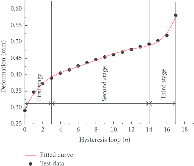
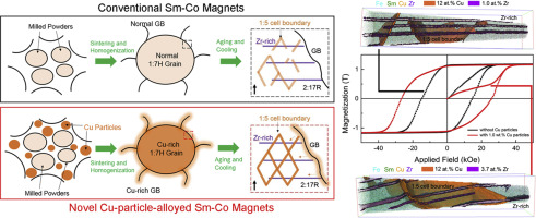
Changes in microstructure, in the form of additional magnetic inclusions such as second-phase particles with different magnetic properties from those of the matrix material, cause changes in the hysteresis properties by introducing more pinning sites that impede domain-wall motion and thereby lead to increased coercivity and hysteresis loss. The same is also true of dislocations when their number density is increased by plastic deformation, either in tension or compression.
So, for example the addition of carbon in the form of iron carbide particles increases coercivity and hysteresis loss. Cold working of the material has a similar effect. The effect of these pinning sites is expressed via the coefficient k in the theory of ferromagnetic hysteresis. Clearly as their numbers increase k will increase proportionally and this results in an increase in the coercivity He. In the low field limit the coercivity is He = k and consequently the coercivity is proportional to the product of number density and average pinning energy per site.
Article src: Introduction to Magnetism and Magnetic Materials (1nd edition), David Jiles, Chapman & Hall/CRC, 1991.
Nature of domains

In a ferromagnetic domain, there is parallel alignment of the atomic moments. In a ferrite domain, the net moments of the antiferrimagnetic interactions are spontaneously oriented parallel to each other (even without an applied magnetic field). The term, spontaneous magnetization or polarization is often used to describe this property.
Each domain becomes a magnet composed of smaller magnets (ferromagnetic moments). Domains contain about 1012 to 1015 atoms and their dimensions are on the order of microns (10-4 em). Their size and geometry are governed by certain considerations. Domains are formed basically to reduce the magnetostatic energy which is the magnetic potential energy contained in the field lines (or flux lines as they are commonly called) connecting north and south poles outside of the material. Figure (1) shows the lines of flux in a particle with a single domain. The arrows indicate the direction of the magnetization and consequently the direction of spin alignment in the domain. We can substantially reduce the length of the flux path through the unfavorable air space by spitting that domain into two or more smaller domains. This is shown in Figure (2). This splitting process continues to lower the energy of the system until the point that more energy is required to form the domain boundary than is decreased by the magnetostatic energy change. When a large domain is split into n domains, the energy of the new structure is about I/nth of the single domain structure. In Figure (2), the moments in adjacent domains are oriented at an angle of 180o to each other. This type of domain structure is common for materials having a preferred direction of magnetization.
Article src: Handbook of modern ferromagnetic materials, A. Goldman, B.S., Springer Science+Business Media New York, Ferrite Technology Worldwide, (1st edition), 1999.
Nucleation of domain walls

Img src
This whole process of wall nucleation and wall motion has its beginnings in spin rotation, on a few atoms at the surface, against the crystal anisotropy forces, and this requires a field equal to 2K/Ms. The essential point is that the process of nucleating a domain wall in a perfect crystal is just as difficult as coherent rotation. Either process requires spin rotation against the same anisotropy forces.
The assumption is that a saturated crystal larger than Ds will break up into domains when the saturating field is reduced to zero, in order to lower its magnetostatic energy. In a perfect crystal this may not be true, because the difficulty of wall nucleation is an energy barrier between the single-domain state and the lower-energy, multidomain state.
Therefore various methods have been employed to provide nucleation sites for domain walls: mechanical scratches, chemical etches, spark erosion, and laser scribing. The best and most practical procedure seems to be laser scribing to produce a series of parallel lines arrayed perpendicular to the rolling direction of the sheet, spaced a few millimeters apart.
Magnetization reversal in ferrite magnets must therefore take place by wall nucleation and motion. The coercivity could in principle be increased by making the particles smaller and/or smoother and with fewer crystal imperfections, in order to decrease the number of sites for wall nucleation.
The necessity for small particles is attributed to the reduced number of domain nucleation sites in a small particle, plus the fact that in magnetically isolated particles a freely moving domain wall can reverse the magnetization direction of only a single particle.
Article src: Introduction to Magnetic Materials (2nd Edition), B. D. Cullity, C. D. Graham, Wiley-IEEE Press, 2008.
Plastic deformation (Cold work)
Img src
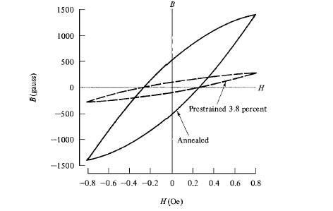
Plastic deformation makes magnetization more difficult. The M, H (or B, H) curve is lower than that for the fully annealed condition. The hysteresis loop rotates clockwise, becomes wider (larger coercivity), and has a bigger area (larger hysteresis loss) for the same maximum value of M (or B). The mechanical strength and hardness also increase. Cold-working is generally possible only for metals and alloys; ceramics are brittle materials and will break rather than deform under stress.
These several changes are caused by the increased numbers of dislocations and other lattice defects. In polycrystalline materials, severe cold work multiplies the dislocation density by a factor of about 104. The resulting microstress impedes both domain wall motion and domain rotation, increasing the magnetic hardness. It also impedes the motion of the dislocations themselves and the generation of new dislocations, thus increasing the mechanical hardness. In the low-field region the effect of cold work is illustrated by figure, which applies to the hydrogen-annealed ingot iron mentioned earlier.
Note that the coercive field Hc is the same for both the annealed and prestrained specimens, which is unusual. This agrees with the fact that mi/ν was found to be independent of strain in this material. The Rayleigh equations predict that Hc, for a given value of Hm, depends only on the ratio of μi to ν and not on the individual values of these constants.
Article src: Introduction to Magnetic Materials (2nd Edition), B. D. Cullity, C. D. Graham, Wiley-IEEE Press, 2008.
Thin films
Img src
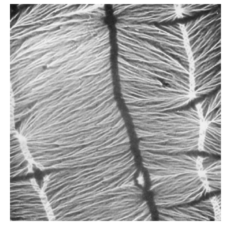
The structure of thin films is complex and hard to characterize. The grain size of films is usually small, of the order of 1000Å or less, which is about 1/100th the grain size of most bulk materials. Since the grain size is comparable to the domain wall thickness, domain walls may extend through many grains and the domain walls lose their crystallographic identity. Preferred orientation (texture) may or may not be present, depending on deposition conditions and nature of the substrate. If a texture is present, it is a single or multiple fiber texture, with fiber axes such as <100>, <111>, etc., usually normal to the plane of the film.
Such a texture introduces no crystallographic anisotropy in the plane of the film. Even if it did, little magnetic anisotropy would result in the case of 80 Permalloy in which the magnetocrystalline anisotropy is close to zero.
Directional structures can be produced in a film if the deposition conditions are arranged so that the direction of the incoming atoms makes an angle with respect to the film plane. This directionality may be the result of crystallographic texture in materials with significant crystal anisotropy, or of geometrical structures produced in the film.
The difference in thermal expansion coefficients between film and substrate leads to stresses in the film (and small stresses in the substrate), and the film itself has microstress due to various imperfections. The effect of these stresses is minimized by choosing a film composition with magnetostriction is as close as possible to zero. Stress anisotropy is therefore avoided because magneto-elastic effects are always proportional to the product of the magnetostriction l and the stresss.
Article src: Introduction to Magnetic Materials (2nd Edition), B. D. Cullity, C. D. Graham, Wiley-IEEE Press, 2008.
Wires
Img src
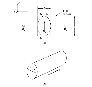
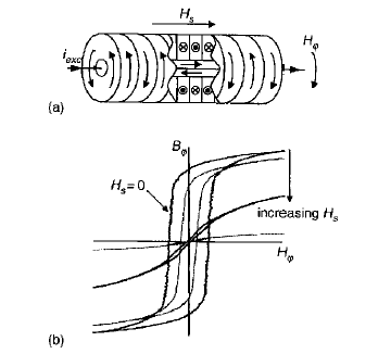
The development of novel materials, such as amorphous ribbons and wires and thin-film multilayers, has opened new perspectives in the domain of magneto-inductive field sensors. Basically, with these materials one can realize devices where the magnetization process, dominated by the presence of induced uniaxial anisotropies, is driven by an AC field generated by a current circulating in the ferromagnetic sample itself and has features dependent on the presence of an external DC field. Such a field can affect the AC permeability and it can therefore be revealed by taking the sample as a circuit element and by measuring the variation of the voltage drop through it. This effect is especially relevant in the near-zero magnetostriction Co-based amorphous wires (having, for example, composition Co69Fe4B15Si12 and small negative saturation magnetostriction, which display a domain structure in the demagnetized state as shown in figure (a). This structure, which is determined by the anisotropies due to the stresses frozen in during the rapid solidification and the condition of free poles avoidance in the material, consists of outer shell antiparallel domains, where the magnetization is circumferentially directed, and axially directed domains at the wire core. The circular field generated by an AC current of frequency f flowing in the wire causes the circumferential domain walls to oscillate and gives rise to the hysteresis loop (Bφ, Hφ), as shown in the example of figure (b). Given the soft behavior of these walls, characterized by coercivities around some 10- 50 A/m, peak current values of the order 10-50 mA are sufficient to complete most of the reversal (with typical wire diameters 30-130 μm).
Article src: Measurement and Characterization of Magnetic Materials, F. Fiorillo, Istituto Elettrotecnico Nazionale Galileo Ferraris, Torino, ITALY, Elsevier Series in Electromagnetism, 2004.